
The common rail injector is the most advanced precision fuel delivery component in modern diesel engines. It operates under ultra-high pressure conditions (up to 2,700 bar) and is controlled by the ECU to achieve precise fuel injection timing, quantity, and atomization.
Inside the injector, multiple mechanical, hydraulic, and electromagnetic systems work together in perfect synchronization. Even a micron-level deviation in any component can affect combustion efficiency, emissions, and engine performance.
This guide provides a complete engineering breakdown of common rail injector components, structure, working principle, solenoid valve function, failure symptoms, and repair insights, designed for technicians, engineers, and diesel system professionals.
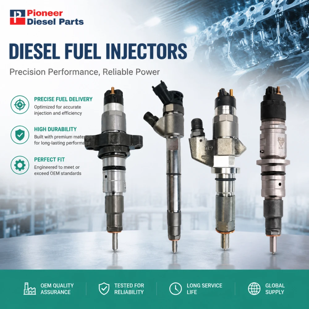
1. What Are Common Rail Injector Components?
A common rail injector is composed of several precision-engineered subsystems that work together to control high-pressure fuel delivery.
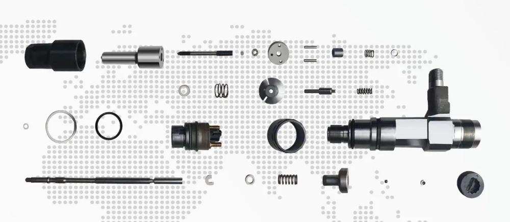
Core components include:
- Injector housing (main structure)
- Solenoid valve system (electromagnetic actuator)
- Control valve assembly (fuel metering system)
- Valve assembly (hydraulic switching unit)
- Nozzle assembly (fuel atomization system)
- Shims and sealing elements (precision adjustment parts)
Each part plays a specific role in regulating fuel flow from the rail to the combustion chamber.
2. Common Rail Injector Structure Diagram Explained
A common rail injector can be understood as a layered pressure-control system.
Fuel flow architecture:
High-pressure fuel → Injector housing → Control chamber → Control valve system → Spill port → Needle valve → Nozzle → Combustion chamber
Functional breakdown:
- Upper section: Solenoid actuator system (electrical control)
- Middle section: Hydraulic pressure control system
- Lower section: Injection and atomization system
This layered structure ensures that electrical signals are converted into precise hydraulic movement.
3. How a Common Rail Injector Works
The working process is based on ECU-controlled pressure differential:
- High-pressure fuel enters injector housing
- Fuel fills control chamber and nozzle passage
- ECU sends electrical signal to solenoid coil
- Armature lifts under electromagnetic force
- Spill port opens, releasing control chamber pressure
- Pressure drops above needle valve
- High-pressure fuel pushes needle upward
- Fuel is injected into combustion chamber
- ECU stops signal, solenoid closes
- Pressure restores, needle returns to seat
👉 This cycle can occur multiple times per combustion cycle in modern systems.
4. Detailed Breakdown of Common Rail Injector Components
4.1 Injector Housing (Structural Pressure Body)
The injector housing is the mechanical backbone of the system.
Function:
- Supports all internal components
- Maintains structural integrity under extreme pressure
- Provides fuel channels and sealing surfaces
Engineering detail:
Most housings are made from alloy steel (e.g., 20CrMo) and undergo carburizing and quenching to improve fatigue resistance.
Failure symptoms:
- External fuel leakage
- Structural cracks (rare but critical failure)
- Corrosion due to contaminated diesel
4.2 Solenoid Valve (Electromagnetic Control Unit)
The solenoid valve acts as the electronic switch of the injector.
Function:
- Converts ECU electrical signals into mechanical movement
- Controls armature lift and spill port opening
Working principle:
- Energized → magnetic force lifts armature → fuel pressure release
- De-energized → spring force closes valve → injection stops
Failure symptoms:
- No injection (coil failure)
- Delayed response
- Engine starting issues
4.3 Control Valve (Fuel Metering System)
The control valve regulates fuel pressure inside the control chamber.
Function:
- Controls pressure balance speed
- Determines injector opening and closing response
Technical insight:
The balance between inlet and outlet flow determines injection precision and fuel quantity.
Failure symptoms:
- Unstable idle
- Incorrect injection volume
- Poor fuel economy
4.4 Valve Assembly (Hydraulic Switching Core)
This is the mechanical switching system inside the injector.
Components:
- Ball valve
- Armature shaft
- Valve seat
- Return spring
Function:
- Controls spill port opening and closing
- Enables pressure differential creation
Failure symptoms:
- Excess return fuel
- Internal leakage
- Injector sticking
4.5 Nozzle Assembly (Fuel Atomization End Unit)
The nozzle is responsible for final fuel spray into the combustion chamber.
Function:
- Atomizes fuel into fine droplets
- Controls spray pattern and penetration
Technical detail:
Modern injectors achieve droplet sizes below 10 microns under 2,700 bar pressure.
Failure symptoms:
- Black smoke
- Poor combustion efficiency
- Power loss under load
4.6 Shims (Precision Adjustment System)
Shims control micron-level mechanical calibration inside the injector.
Main types:
- Armature lift shim
- Buffer shim
- Spring force shim
Function:
- Adjust valve stroke
- Control spring preload
- Fine-tune injection timing
Failure symptoms:
- Incorrect injection timing
- Excess return flow
- Weak injection pressure
5. Component Interaction System (How Everything Works Together)
The injector operates as an integrated system:
- ECU (Brain): Sends control signals
- Solenoid (Trigger): Activates mechanical movement
- Control valve (Regulator): Adjusts pressure balance
- Valve assembly (Switch): Opens/closes fuel path
- Nozzle (Output): Performs final injection
👉 Any deviation in one component affects the entire injection cycle.
6. Common Rail Injector Failure Symptoms & Root Causes
| Symptom | Root Cause |
|---|---|
| Hard starting | Solenoid coil failure |
| Black smoke | Nozzle wear or blockage |
| Rough idle | Control valve instability |
| Power loss | Pressure imbalance |
| Excess return fuel | Valve seat wear |
| Engine knocking | Incorrect injection timing |
| DPF regeneration issues | Injection quantity error |
7. Repair & Maintenance Guide
A proper diagnostic workflow is essential for injector repair:
Step 1: Electrical diagnosis
- Check solenoid coil resistance
- Verify ECU signal output
Step 2: Hydraulic test
- Measure return fuel volume
- Check pressure consistency
Step 3: Mechanical inspection
- Inspect nozzle spray pattern
- Check valve movement
Step 4: Precision calibration
- Adjust shim thickness
- Verify lift stroke accuracy
👉 Fuel contamination is the leading cause of injector failure worldwide.
8. Internal Linking Strategy
To build topical authority, this page should link to:
Core pages:
Supporting articles:
- 0445120007 Common Rail Injector – High Duty Cycle Guide for City Buses & Delivery Trucks
- DLLA142P1709 Common Rail Nozzle – Specs, 0445120121 Injector Fitment & Cummins ISLe Guide
- F00RJ01479 Valve Assembly – Complete Guide: Compatibility, Symptoms & Replacement
9. Frequently Asked Questions
Q1: What are the main components of a common rail injector?
A: The injector consists of housing, solenoid valve, control valve, valve assembly, nozzle, and shims, all working together to control fuel injection precisely.
Q2: How does a common rail injector solenoid valve work?
A: The ECU energizes the solenoid coil, lifting the armature and opening the spill port. This reduces pressure in the control chamber, allowing fuel injection to begin.
Q3: What is the function of the injector control valve?
A: It regulates fuel flow into the control chamber, controlling injection timing, pressure balance, and fuel quantity.
Q4: What causes common rail injector failure?
A: The main causes are fuel contamination, worn valve seats, solenoid coil failure, nozzle blockage, and incorrect shim calibration.
Q5: What are the symptoms of a bad injector?
A: Common symptoms include rough idle, black smoke, power loss, excessive return fuel, and engine knocking.
Q6: How long does a common rail injector last?
A: Under proper fuel conditions, injectors can last several hundred thousand kilometers, but contamination can significantly reduce lifespan.
Q7: What is the latest trend in injector technology?
A: Modern injectors are moving toward 2,700+ bar ultra-high pressure systems, multiple injection cycles, and improved electromagnetic efficiency.
10. Conclusion
The common rail injector is a highly advanced precision system that integrates mechanical, hydraulic, and electromagnetic technologies to achieve ultra-accurate fuel delivery in modern diesel engines.
Its performance depends on the perfect coordination of multiple components including the injector housing, solenoid valve, control valve, valve assembly, nozzle, and precision shims. Even microscopic wear or contamination in any single component can significantly affect engine performance.
As diesel technology evolves toward higher pressures, cleaner combustion, and multi-injection strategies, the role of common rail injectors becomes even more critical in meeting global emission standards and efficiency requirements.
Understanding these components not only improves diagnostic accuracy but also helps extend injector lifespan and optimize engine performance in real-world applications.
